
Blog-Kategorien
kürzliche Posts
If your power supply fails an EMC test, your motor drive emits radiated noise, or your charger shows interference on sensitive signal lines, the component that usually fixes the common-mode side of the problem is a common mode choke (also called a EMI/EMC common mode inductor). It sits at the front end of the circuit and quietly blocks unwanted noise while letting the useful current pass through. In this article we will explain what this inductor is, how it works, and where it is used in real products.
I. What Kind of Inductor Is This?
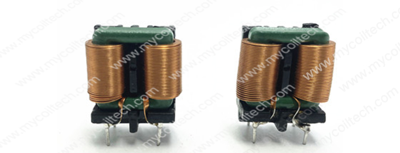
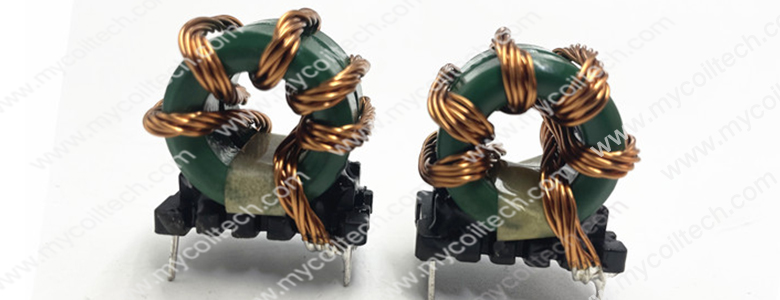
1.A common mode choke is a magnetically coupled inductor with two or more matched windings wound on the same magnetic core. Looking at the samples above, you can recognize the typical construction:
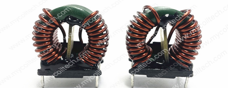
1)A magnetic core (in these samples, a green-coated ring or bobbin core).
2) Two windings with the same number of turns, wound symmetrically, so the two lines are balanced.3) A plastic base or enclosed housing with through-hole pins for PCB mounting.
4)Enameled copper wire, sometimes a single solid wire, sometimes a multi-strand (litz-style) winding for higher frequency and higher current.
2.To understand its job, you first need to separate two kinds of current on a wire pair:
1)Differential mode current is the useful current that goes out on one line and returns on the other. It carries power or signal and must pass through the circuit with as little loss as possible.
2)Common mode noise is unwanted current that flows in the same direction on both conductors, returning through ground or parasitic capacitance. It is the source of conducted and radiated EMI.
II. How a Common Mode Choke Works
The principle comes down to how the magnetic fields from the two windings behave:
1. For common mode noise, the fields add up. When common-mode current flows in the same direction through both windings, the magnetic fields generated by the two coils reinforce each other. The combined field creates a high impedance against that noise, so the choke acts like a barrier: it resists the unwanted common-mode current and reduces its amplitude before it can leave the equipment or couple into neighboring circuits.
2. For differential mode current, the fields cancel out. The useful current flows in opposite directions in the two lines, so the magnetic fields from the two windings cancel each other. The choke therefore presents very low impedance to the differential current, letting normal power or signal pass through with minimal attenuation and little impact on circuit efficiency.
3. Core and winding decide the noise band. The suppression is frequency-dependent. A choke is optimized to show high impedance over the noise band you need to clean up. Core material, wire type, turns count and winding structure all shape the impedance curve:
1)MnZn ferrite cores are widely used for low-to-medium frequency noise and offer a good balance of performance and cost.
2)Nanocrystalline cores provide strong high-permeability suppression, especially for low-frequency common-mode noise and high-current designs.
3)Multi-strand / litz wire reduces skin-effect loss at higher frequencies; flat or thick wire is used where through-current and thermal rise are the limits.
III. Where the Common Mode Choke Is Used — Real-World Examples
1.EV On-Board Chargers (OBC) and Charging Piles
Electric vehicles carry high-power power conversion (OBC, DC-DC converter, traction inverter) and strict automotive EMC requirements.
Such as:
1) In an 11–22 kW on-board charger, a common mode choke is placed on the AC input and sometimes on the DC side to suppress noise generated by the PFC and switching stages. Automotive designs target limits such as CISPR 25 Class 5, operate over −40 °C to +105 °C, and often require AEC-Q200 qualification. High-current versions use nanocrystalline or ferrite cores and flat/multi-strand winding to retain impedance under DC bias.
2)In a DC fast charger, CM chokes may be required on both the AC grid interface and the DC output to the vehicle.
Role: high-current common-mode filtering, insulation and thermal reliability in the vehicle and charging station.
2.LED Drivers and Lighting Power Supplies
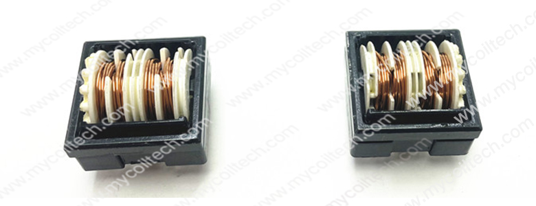
LED drivers are switch-mode converters, and long cables between the driver and the LEDs act as antennas for common-mode noise.
Example: A panel-light or street-light LED driver uses a small common mode choke on its input to keep conducted and radiated noise under control, helping the luminaire meet lighting EMC standards and avoiding visible flicker or interference with nearby control circuits.
Role: compact low-to-medium current filtering, low leakage, stable operation over the driver's lifetime.
Appliances: Washing machines, air conditioners and refrigerators use their own inverters and control boards; CM chokes keep noise away from the mains and from sensitive sensors.
Telecom / data center PSU: Server and communication power supplies use two-stage ferrite or nanocrystalline chokes to achieve high density and low-profile filtering while meeting conducted-emission limits.
Medical equipment: Medical power supplies need low leakage current and comply withIEC 60601-1-2; the choke works together with carefully chosen Y capacitors to control line-to-ground current.
IV. Comparison of the Choke Styles in These Samples
|
Style |
Visible construction |
Typical through-current |
Best-fit application |
|
Vertical bobbin dual-coil choke |
Two separated coils on a vertical bobbin/dual-column core, straight pins |
Medium current, good winding balance |
Power supply input filtering, consumer and industrial electronics |
|
Ring core, two matched solid-wire windings, through-hole base |
Low-to-medium current, general purpose |
AC-DC adapters, industrial PSU, LED drivers |
|
|
Toroidal multi-strand high-current choke |
Ring core wound with multiple copper strands, multi-pin base |
Higher current, higher frequency |
EV OBC, high-power PSU, PV/ESS converters |
|
Enclosed horizontal bobbin choke |
Small enclosed housing, horizontal slotted bobbin, fine wire |
Low current, compact footprint |
Auxiliary/signal filtering, compact consumer and lighting boards |
V. Selection Checklist
1)Noise band and target limit: identify the frequency range of the common-mode noise and the EMC standard the product must meet (e.g., CISPR 32, CISPR 11, CISPR 25).
2)Impedance at your noise frequency: check the impedance-frequency curve, not just the rated inductance; impedance should peak where the noise is strongest.
3)Rated current and DC bias: make sure the choke carries the normal operating current without core saturation, which would drop impedance and weaken suppression.
4)Core material: MnZn ferrite for general low-to-medium frequency use; nanocrystalline for high permeability, high current and low-frequency suppression.
5)Wire and package: solid wire, multi-strand/litz or flat wire according to current and frequency; through-hole or SMD, vertical or horizontal, based on board space and assembly.
6)Insulation, temperature and certification: winding-to-core/line insulation withstand voltage, temperature class, and automotive/medical certification when required.
VI. Why Work With Us
As a manufacturer of common mode chokes and inductors, we supplies various toroidal inductors with base for power adapters, EV chargers and OBC, LED drivers, PV and energy-storage converters, industrial drives and consumer electronics. We can tune core material, winding structure, current rating and package to your impedance curve and space constraints.
If you are working on a power supply, charger, driver or inverter and need help choosing or customizing a common mode choke, send us your requirements — operating current, target noise band, impedance target and board size. We will help you find a choke that keeps common-mode noise under control and helps your product pass EMC tests.
Contact: sales008@mycoiltech.com


Hefei Mycoil Technology Co.,LTD (MCT) ist ein High-Tech-und wachsenden Unternehmen, wir sind verpflichtET, die Entwicklung und Produktion von verschiedenen Arten von Spulenprodukten, verschiedene Arten von Filterprodukten. die Bedürfnisse der Kunden ...

2026 Hefei Mycoil Technology Co.,Ltd..All rights reserved

皖公网安备 34019002600405号
 +86(0)55166196829
 sales@mycoiltech.com
 Lily~Mycoiltech